Introduction
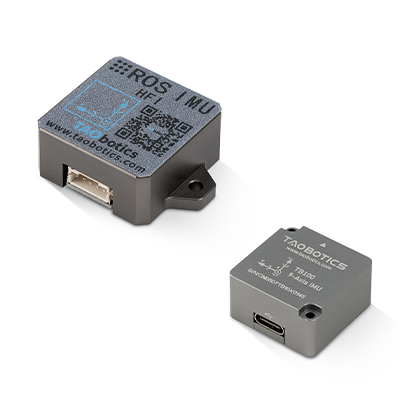
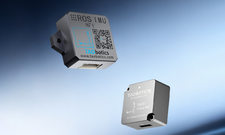
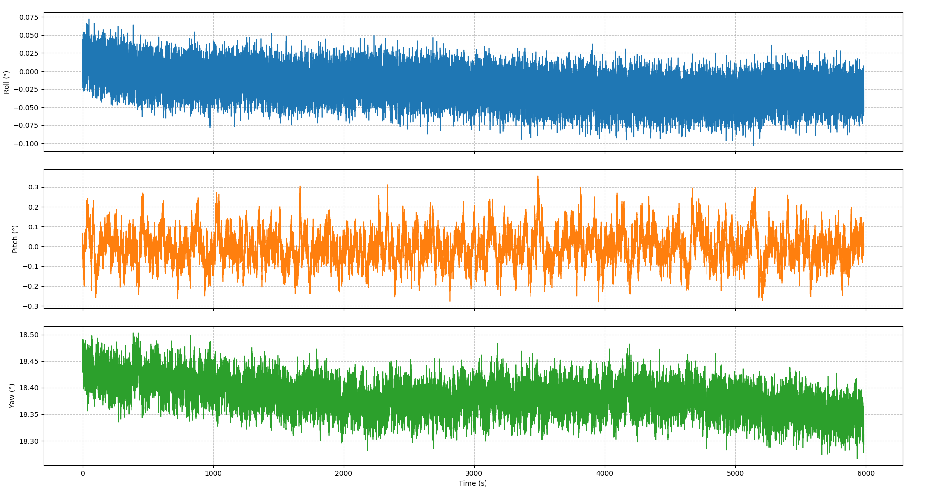
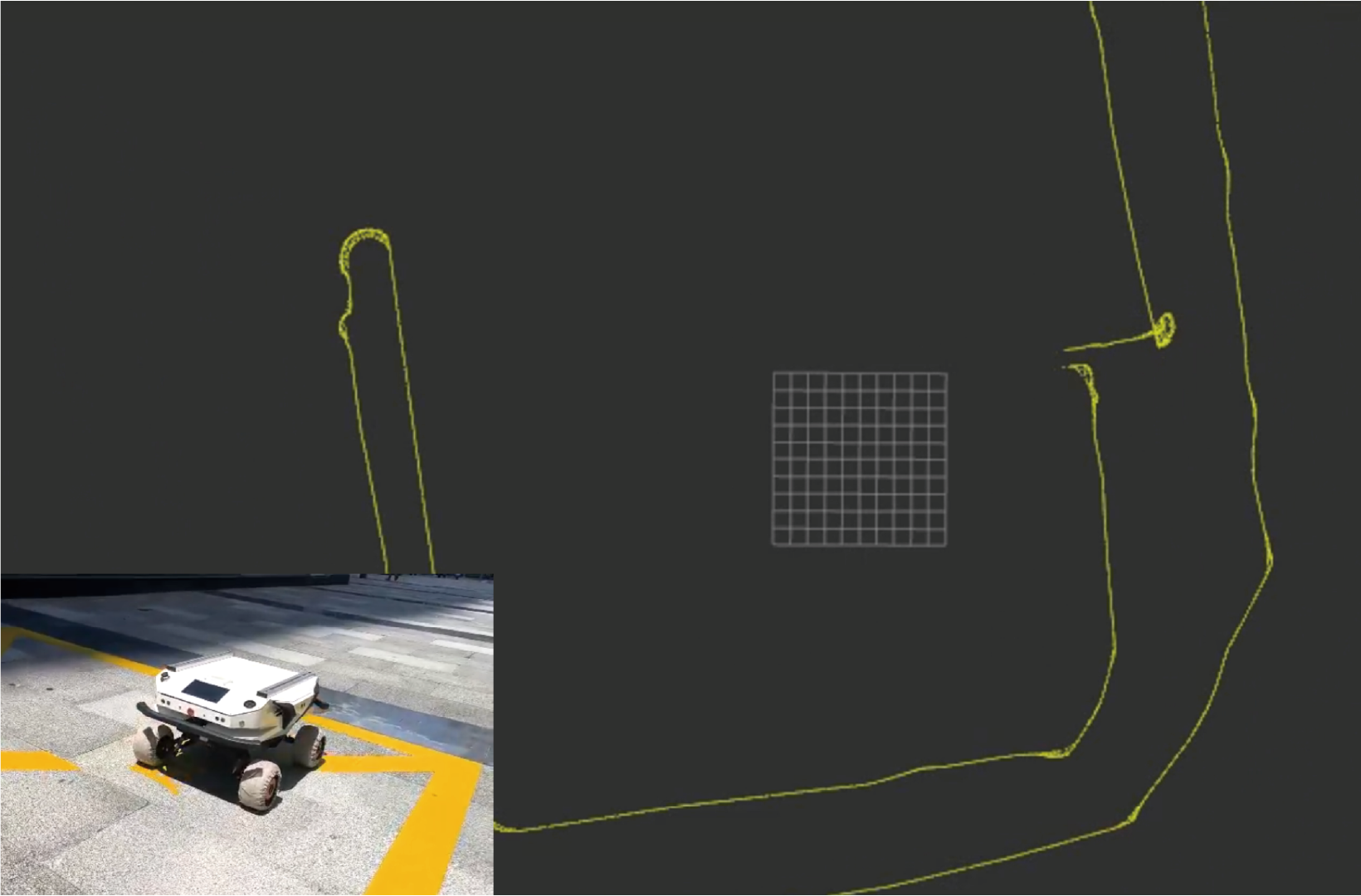
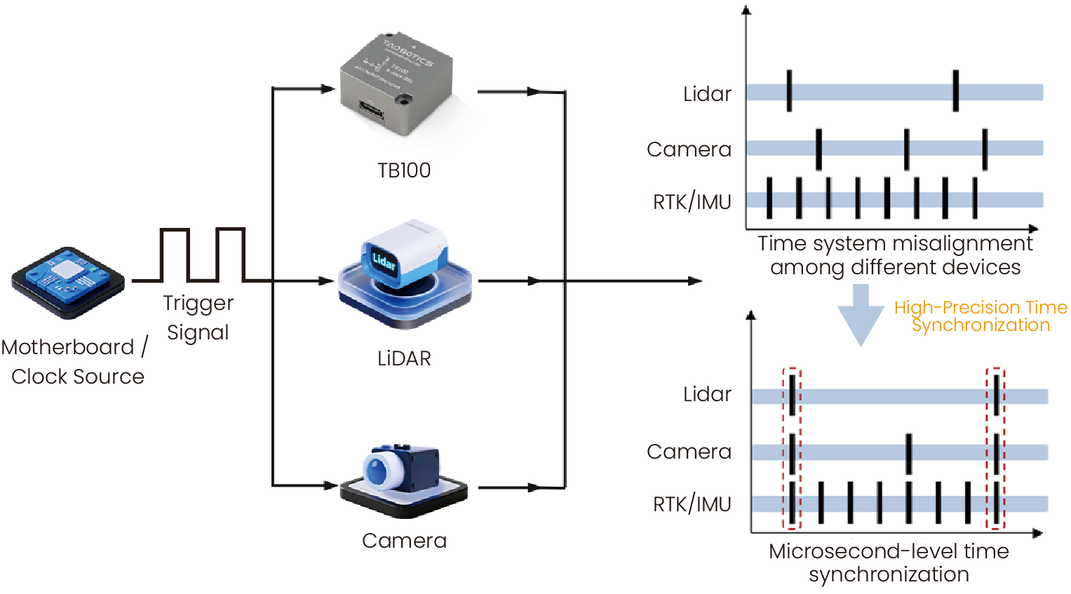
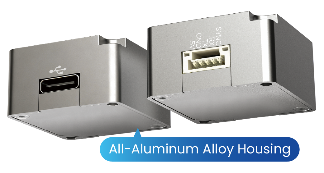
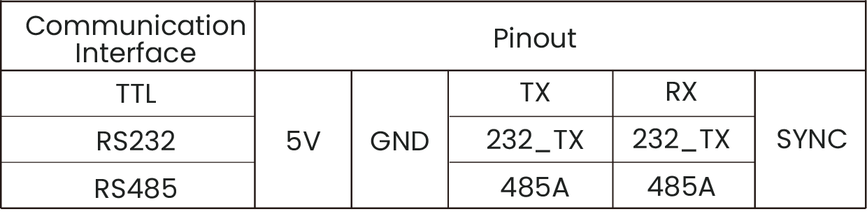
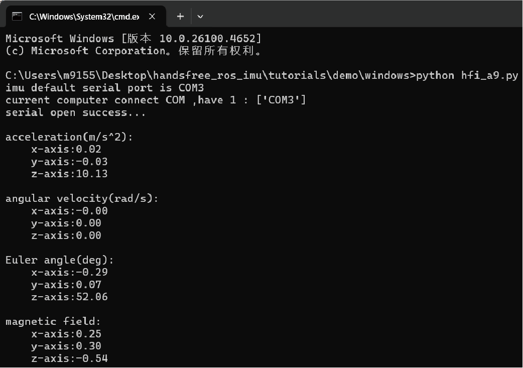
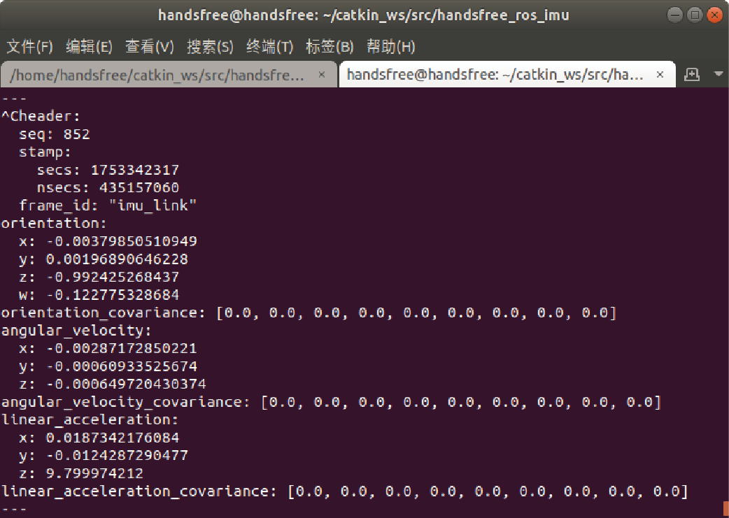
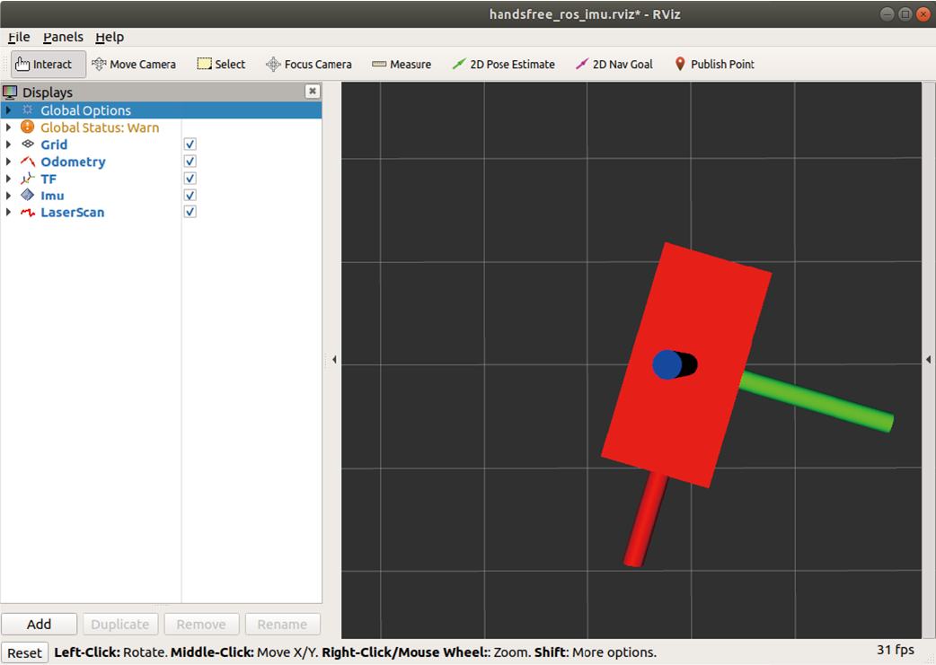
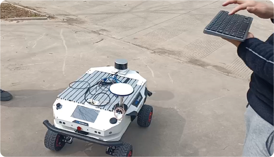
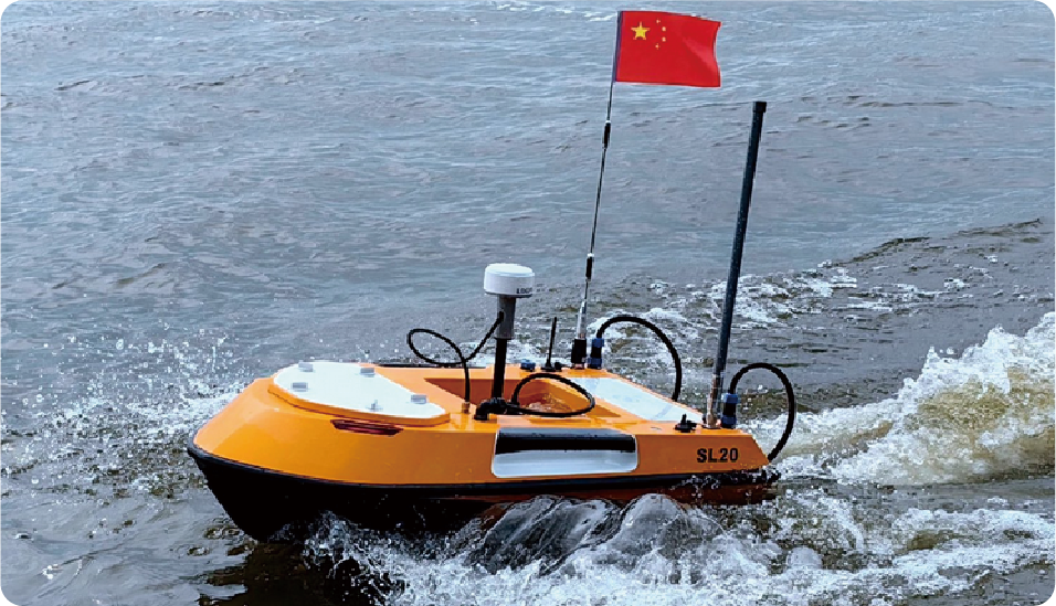
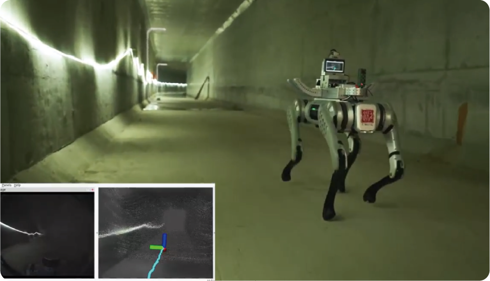
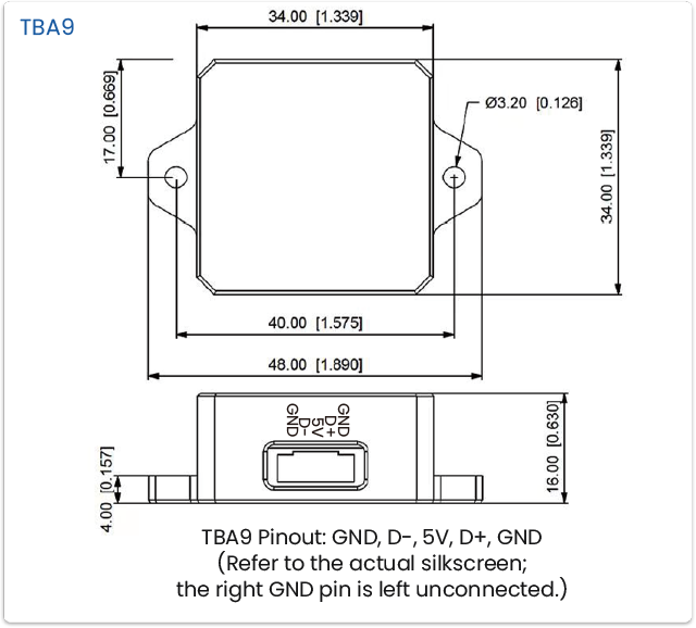
Taobotics TB-Series Industrial 9-Axis IMU features anti-magnetic interference, factory precision calibration, 0.1° RMS high accuracy, and 800 Hz high-frequency output. It supports output of acceleration, angular velocity, magnetometer data, and attitude angles, making it widely suitable for robotics, UAVs, unmanned vehicles, and more. The module offers hardware trigger functionality, enabling microsecond-level synchronization with LiDAR, cameras, RTK, and other devices. It supports multiple communication interfaces (USB-C, TTL, RS232, RS485) and is compatible with ROS, Python, and C++ for seamless integration with various acquisition systems. The upper-computer software allows real-time data display, recording, waveform analysis, and parameter configuration. Built to industrial-grade standards, it delivers exceptional cost-effectiveness.
Product Features

Magnetic-interference immunity

9-axis sensor fusion algorithm

Multiple communication protocols

800 Hz output rate

Roll, pitch, yaw

Hardware IO Triggering

Attitude estimation

Quaternions / Euler angles

Euler angles

Kalman filtering
.png)
ROS-compatible

Secondary development
Designer and manufacturer of mobile robots, shipped to over 50 countries worldwide
Magnetic-interference immunity
Proprietary 9-axis magnetic-disturbance-rejection algorithm, ensuring reliable operation in dynamic magnetic fields (e.g., motors and loudspeakers)
Attitude data remains unaffected by magnetometer interference after fusion
Undeterred by magnetic interference, adapts to complex environments
High-precision factory calibration
Integrates a high-precision 9-DoF fusion algorithm with raw-data–based calibration (nonlinearity and cross-axis/non-orthogonality compensation) to achieve 0.1° RMS accuracy.
Long-term test results of TBA9
Long-term test results of TB100
IMU–wheel odometry fusion delivers ~2 m positional error across 600m.
Microsecond-level hardware trigger (TB100)
Supports microsecond-level I/O hardware triggering, enabling microsecond synchronization with LiDAR,industrial cameras, and RTK sensors, resulting in more accurate SLAM mapping.
Extensive industrial interfaces (TB100)
Supports multiple communication interfaces including USB Type-C, TTL, RS-232, and RS-485.Flexibly compatible with a wide range of devices, including embedded systems, industrial PCs (IPCs), controllers.
Secondary Development
Provides cross-platform drivers for ROS, Python, and C++
Windows Operation
ROS Driver
Rviz Visualization
Host software (PC UI)
The matched upper computer is simple and intuitive, supporting data display, data recording, waveform analysis, parameter configuration, and more. It comes with pre-set parameters for typical scenarios,allowing for one-click configuration based on the application context.
Data visualization
Attitude/orientation,raw data, plots/graphs
Data recording
9-DoF fusion settings
Enable sensors(gyroscope / magnetometer /
accelerometer)
Algorithm parameter tuning
Communication settings
communication rate (Hz)
protocol
Scenario presets
UGV / UAV / USV
Featured in renowned datasets
TBA9 (formerly Handsfree A9) is included in the M2DGR multi-modal robotics dataset (1k+ stars on GitHub).
https://github.com/SJTU-ViSYS/M2DGR
Application Case
IMU & Motor Encoder Fusion Odometry
By fusing IMU data with motor encoder readings, a high-precision odometry system is achieved, ensuring smooth navigation and accurate positioning for unmanned vehicles even in GNSS-denied environments.
RTK & IMU Integrated Navigation: Centimeter-Level Positioning
RTK provides high-accuracy absolute positioning, while the IMU compensates for short-term signal outages. The integrated solution delivers reliable centimeter-level positioning in all weather and complex environments.
Quadrotor UAV Autonomous Flight Attitude Stability
The IMU perceives the drone’s pitch, roll, and yaw angles in real-time, ensuring attitude stability and rapid response control during autonomous flight.
Engineering Vehicle Slope Monitoring
The IMU collects real-time vehicle attitude and tilt data,assisting engineering vehicles in maintaining safe and stable operation on slopes and challenging terrain.
Ship Roll and Pitch Monitoring
The IMU provides real-time monitoring of ship roll and pitch angles, supporting motion control and attitude compensation to enhance safety and comfort during maritime operations.
Handheld 3D Laser Scanner
Combining IMU with LiDAR, the system compensates for hand-shake and pose drift during scanning, improving the accuracy and continuity of 3D point cloud modeling.
Robot Motion Control
Real-time monitoring of the robot’s body posture and acceleration ensures its dynamic dexterity in complex terrains, enabling it to handle various arduous tasks such as inspection, search and rescue, and transportation.
Gait Analysis
In humanoid or quadruped robots, the IMU delivers real-time posture feedback, enabling smooth motion and natural gait patterns.
Technical parameters
| Category | Parameter | TBA9 | TB100 |
| Sensor | 3-axis: Gyroscope | ✓ | ✓ |
| 3-axis: Accelerometer | ✓ | ✓ | |
| 3-axis: Magnetometer | ✓ | ✓ | |
| Features | Sensor Data Fusion | ✓ | ✓ |
| IO Pulse Hardware Trigger | × | ✓ | |
| Parameter Configuration for Scene-based Data Fusion | ✓ | ✓ | |
| Vibration Resistance | ✓ | ✓ | |
| Basic Factory Calibration | ✓ | ✓ | |
| Desktop GUI Configuration Software | ✓ | ✓ | |
| Python Examples & ROS Driver Package | ✓ | ✓ | |
| Interface | USB Interface | ✓ | ✓ |
| 485/232/TTL | × | ✓ | |
| Output | Calibrated Raw Data Output | ✓ | ✓ |
| Roll, Pitch, Yaw Angle Output | ✓ | ✓ | |
| Adjustable Output Frequency | ✓ | ✓ | |
| Typical Performance | Static Accuracy (Roll-Pitch, ° RMS) | <0.1 | <0.2 |
| Static Accuracy (Heading, ° RMS) | <0.5 | <0.8 | |
| Dynamic Accuracy (Roll-Pitch, ° RMS) | <0.5 | <0.8 | |
| Dynamic Accuracy (Heading, °/min) | < 0.1 | < 0.1 | |
| Bias Stability (Roll-Pitch, °/h) | 0.2 | 0.2 | |
| Bias Stability (Heading, °/h) | 5 | 7 | |
| Operating Conditions | Temperature (°C) | -40~85 | -40~85 |
| Electrical & Physical Parameters | Voltage (V) | 5 (Typ.) 4.7~5.3 | 5 (Typ.) 4.7~5.3 |
| Current (mA) | <60 | <150 | |
| Power (W) | <0.3 | <0.8 | |
| Communication | USB TTL Serial Port | USB Type-C (Virtual COM), UART (TTL/RS232/RS485 configurable) | |
| Vibration Range (G) | ±8 | ±10 | |
| Axis Count | 9 | 9 | |
| Dimensions (L x W x H, mm) | 34 x 48 x 16 | 25 x 25 x 9 | |
| Weight (g) | 28 | 16 | |
| Specification | RoHS, IP50 | RoHS, No IP Rating | |
| Housing Material | Aluminum Alloy | Aluminum Alloy | |
| Startup Time (Cold Start, Dynamic Mode, s) | 7 | 3.2 | |
| Startup Time (Cold Start, Static Mode, s) | 15 | 10 ~ 30 (Default 30s, Configurable) | |
| Output Frequency (Hz) | Max 150, Adjustable | Max 800, Adjustable | |
| Serial Baud Rate (bps) | 2400~921600 | USB Type-C Virtual COM (Auto Baud Rate), TTL (2400-921600), RS232 (2400-460800), RS485 (2400-921600) | |
| Gyroscope | Measuring Range (X, Y, Z axis, °/s) | ±2000 | ±2000 |
| Resolution (°/s) | 0.06 | 0.01 | |
| Bandwidth (Hz) | Max 256 | Min 68 | |
| Bias Stability (X, Y, Z axis, °/h) | 10 | 5.5 | |
| Nonlinearity (% FS) | 0.3 | <0.2 | |
| Acceleration Sensitivity (°/s/g) | – | <0.1 | |
| Accelerometer | Measuring Range (g) | ±8 | ±10 |
| Resolution (mg) | 0.2 | 0.4 | |
| Bandwidth (Hz) | 256 | Min 70 | |
| Noise (mg) | ≤50 | ≤12 | |
| Noise Density (µg /√Hz) | 500 | 190 | |
| Bias Instability (mg) | – | 0.05 | |
| Zero Temperature Drift (mg) | – | <5.5 | |
| Nonlinearity (% FS) | 0.5 | 0.5 | |
| Magnetometer | Measuring Range (Gauss) | ±1.3 | ±1.3 |
| Resolution (Gauss) | 0.001 | 0.001 | |
| Internal Sampling Rate (Hz) | Max 160 | Max 75 | |
| Nonlinearity (% FS) | 0.1 | 0.1 |


